Reducing material volume is a necessity in additive manufacturing. Using excess material in your part is a waste and can be costly no matter what your printing method looks like. This material reduction process could be termed as “lightweighting” but many people are more familiar with the concept of creating “infill.” Nomenclature is a little unclear here but we’re talking about the same thing.
A typical infill is a low material-density pattern that replaces solid volumes in an additive part to reduce material usage. FDM manufacturing typically has infill created by slicing software when preparing the part for printing. The infill pattern is process specific and is created automatically with some user input. The chosen pattern fills large volumes of the part that would otherwise be printed solid.
If you’re not working with a FDM process or slicer then you may be at a loss for how to infill parts. It’s still a necessary step if you want to save on printing costs. It is possible with software such as Meshmixer or nTopology but these may complicate your design flow or be overkill for your application.
The good news is that infill can be created natively in your solid design package. Native infill creation can be difficult at times but the process provides complete control over the pattern, parameters, and orientation. Having complete control over the infill appearance is one of the primary benefits of creating it natively. Unique and eye catching infill designs present an opportunity for branding and are only limited by your creativity and printing process.
Knowing the limitations of your additive process will guide wall thicknesses and element spacing. 2D patterns are easier to design but creating 3D lattice infill is possible. Appearance, material usage, strength or other mechanical properties can all be optimized by changing patterns or parameters.
The following example is for Solidworks but the process should be similar in other solid CAD packages. There are a few different methods to achieve the same effect but this version is robust and will be tolerant of changes to your design. The key to the process is working with separate solid bodies.
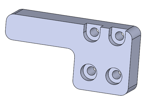
1) Create your part as a normal solid
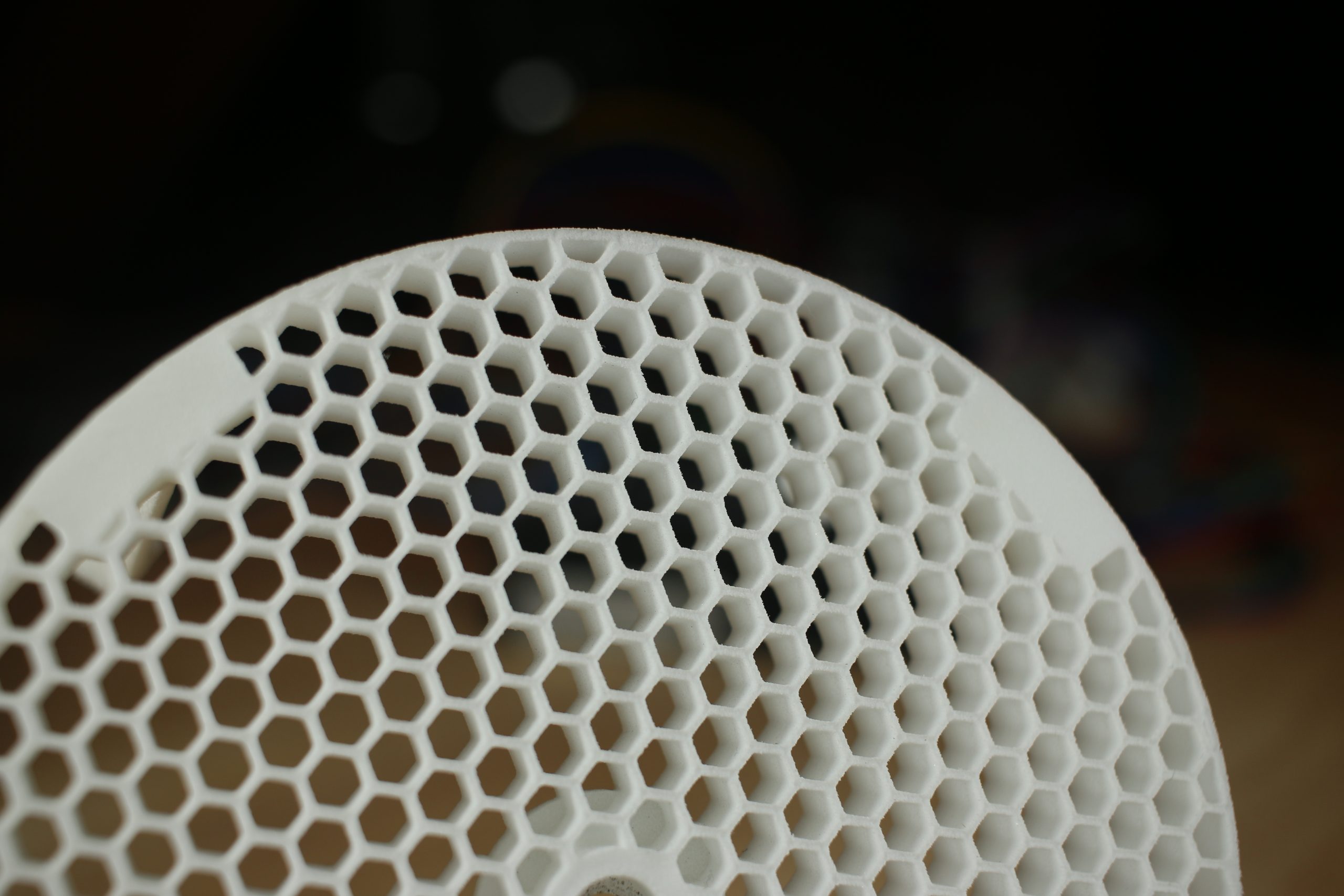
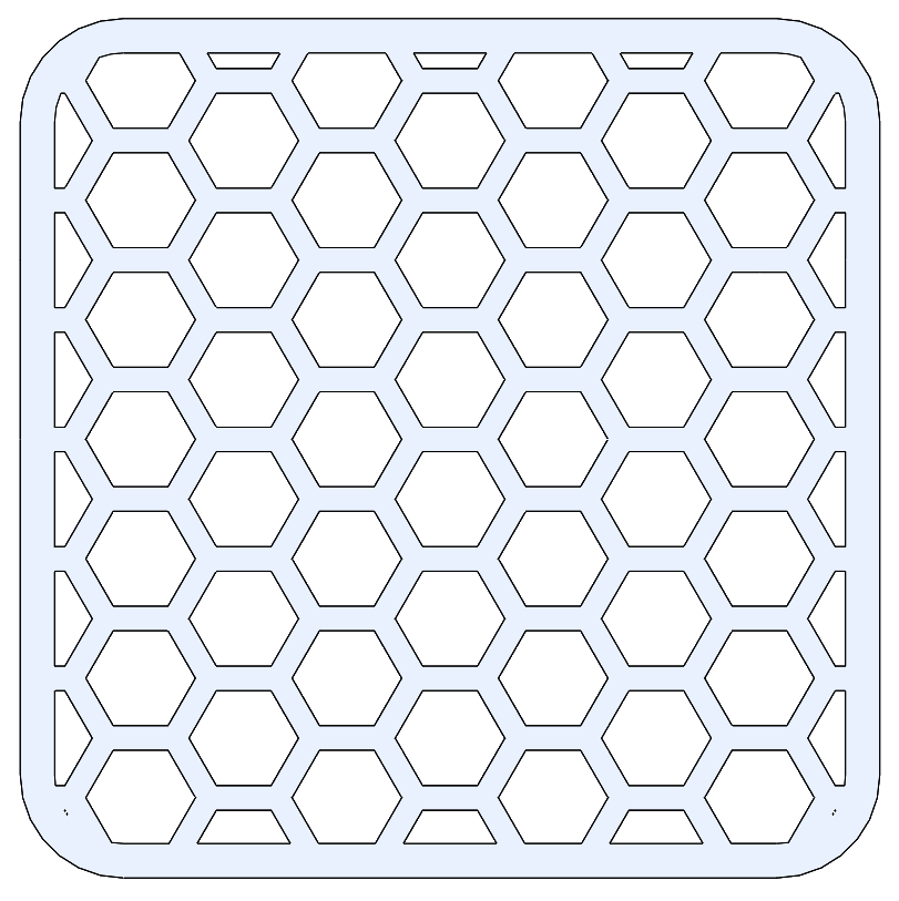
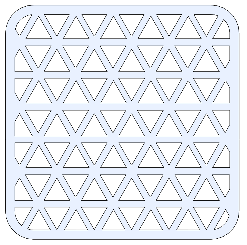
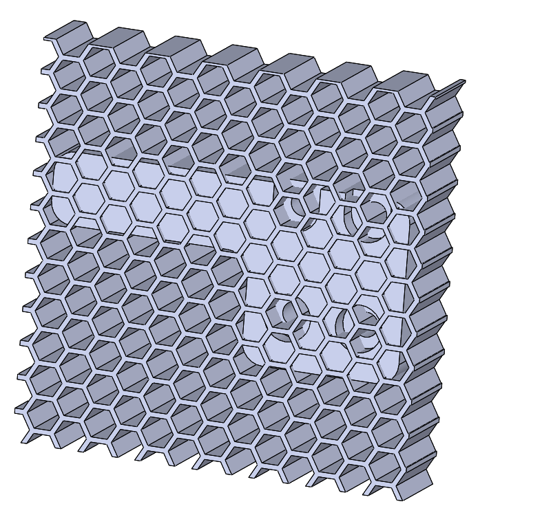
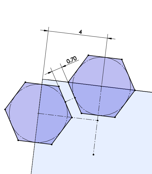
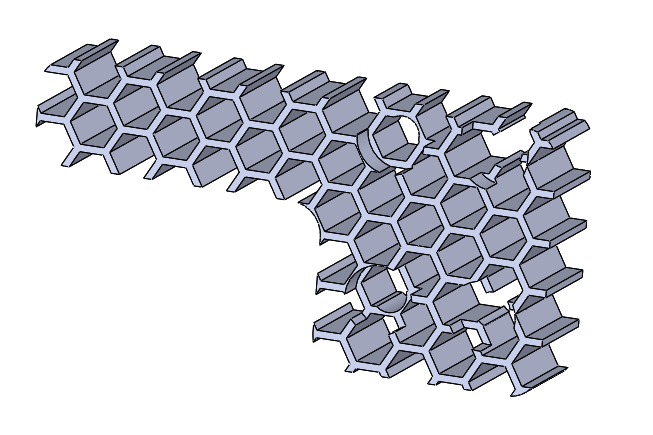
2) Create a large block with your lightweight pattern as a new solid body. Do not “merge result” when creating the new extruded solid. Create a simple extrude-cut and pattern it across the new solid. Hexagons are great for creating a lightweight honeycomb style print.
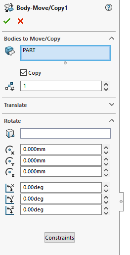
3) Create a copy of your original solid part body
4) Combine your lightweight pattern with one of the part bodies in a “common” operation. This will create a version of your part using the lightweight pattern.
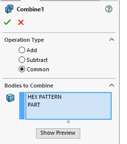
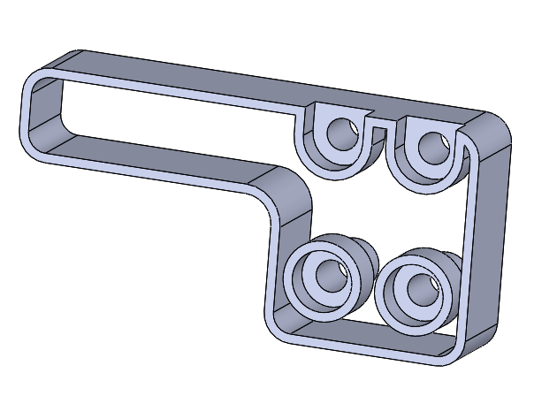
5) Shell the second part body to create a stripped down “walls only” version of your part.
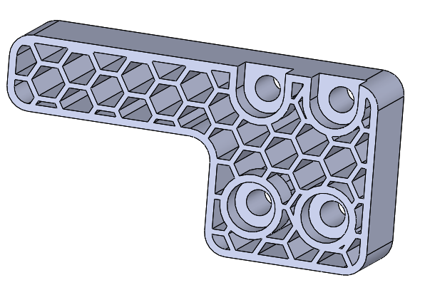
6) Perform an additive combine to merge the lightweighted body with the shelled body
It can be a time saver to build a library of these lightweight patterned blocks. You can use them as templates when starting new parts.