I’ve been daydreaming about some 3D printing projects again and have spent some time looking at the lattice style structures that are used as low density volume fillers in SLA or SLS prints. I think this is an underappreciated area of printing because these structures can only be created practically by printing and there is likely some interesting strength and stiffness optimizations you can do by tinkering with the lattice geometry. I think this will become much more interesting as flexible material prints become more popular.
These lattice structures are pretty simple geometrically so in theory you could create them in Solidworks but in practice I think it would be tedious and a bit of a pain. The geometry should be easy to generate with a few lines of code so I thought it would be interesting to see if I could generate some geometry programmatically and then import it into Solidworks. After doing some research I couldn’t find an existing method of doing this. The closest thing was a few Solidworks macros to import point clouds.
I’ve found the Solidworks API and associated VBA difficult to work with in the past. In theory I could generate all my geometry just using some VBA in a Solidworks macro but I think that would be an exercise in frustration for myself.
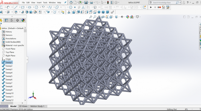
I decided to do most of the heavy lifting outside Solidworks and then write a macro to import the geometry and create some simple swept cylinder features to replicate my geometry. I’ve done some 3D work in Processing before so I expected the geometry creation to be straightforward by reusing some existing code.
Here’s a quick overview of the plan I developed:
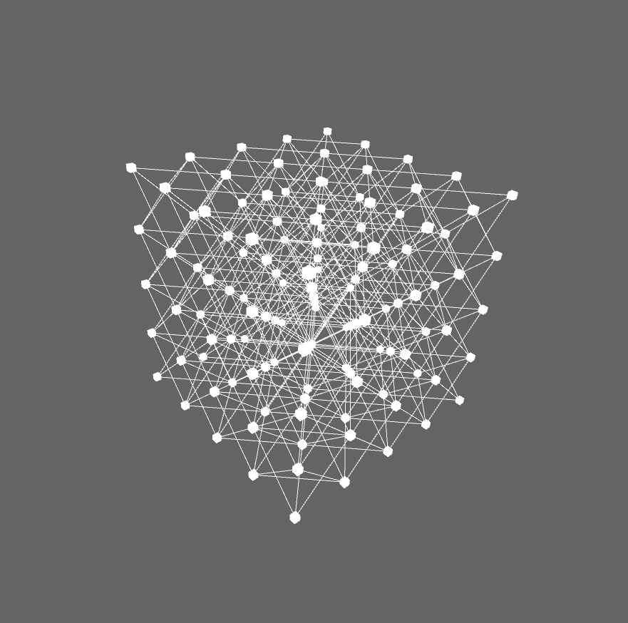
- Generate line geometry in Processing
- Export lines as pairs of 3D points and a diameter parameter
- Use a Soldiworks macro to create 3D sketches based on the points, then create a swept circular profile for each
Predictably the Solidworks macro was the most difficult part for myself. It imports data from a text file with each line defined by Diameter, X1, Y1, Z1, X2, Y2, Z2. It creates a 3D sketch, inserts a line, then performs a circular profile sweep (SW 2017 and later). Overall it’s pretty crude.
The macro works OK but could use some improvement. The swept cylinders end with flat surfaces which creates gaps at intersections. Ideally each cylinder would have a spherical end to reduce gaps.
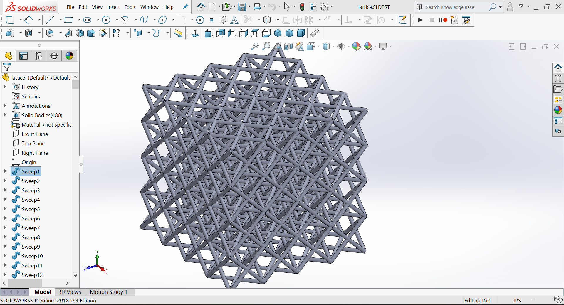
Each cylinder is created as a separate body by design. This allows the lattice to be easily trimmed in Solidworks without leaving any weird partial bodies.
Overall this was a fun project. I don’t have any immediate plans for this work but I think I’ll dust off this code in the future. If this project interests you I would suggest that you don’t go into the deep end of programming complicated geometry. Mesh Mixer has a lot of high end tools for this type of work.
Here’s the macro code:
Dim swApp As Object
Sub main()Set swApp = Application.SldWorks
Set Part = swApp.ActiveDocDim x As Integer
x = 1
Dim sketch As String‘open file
Open “lines.txt” For Input As #1
Do While Not EOF(1)
Input #1, D, X1, Y1, Z1, X2, Y2, Z2‘create 3d sketch
Part.SketchManager.Insert3DSketch False
‘create line
Set skSegment = Part.SketchManager.CreateLine(X1 / 1000, Y1 / 1000, Z1 / 1000, X2 / 1000, Y2 / 1000, Z2 / 1000)
Part.SketchManager.Insert3DSketch False‘select new line
sketch = “3DSketch” & x
boolstatus = Part.Extension.SelectByID2(sketch, “SKETCH”, 0, 0, 0, True, 4, Nothing, 0)
x = x + 1‘create sweep
Dim myFeature As Object
Set myFeature = Part.FeatureManager.InsertProtrusionSwept4(False, False, 0, False, False, 0, 0, False, 0, 0, 0, 0, False, True, True, 0, True, True, D / 1000, False)Loop
Close #1Set swApp = Application.SldWorks
End Sub