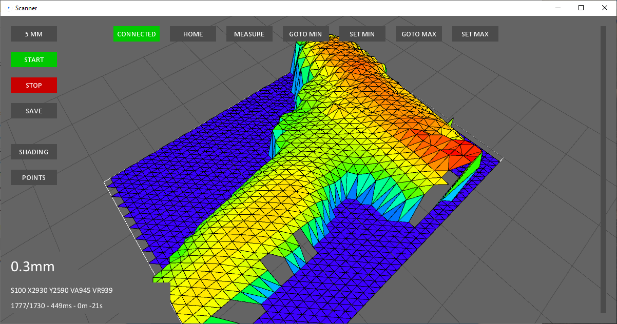
This 3D scanner project is built around a second-hand Baumer OADM SA35 laser displacement sensor. This type of sensor seems to be relatively unknown in the hobbyist maker space and I’m not sure if it’s due to obscurity or the high upfront cost (hundreds of dollars). These sensors have high accuracy, rapid response times, and operate without physical contact. They typically employ a triangulation-based method, utilizing a laser and a sensor to measure the position […]

3D Printing / Mechanical Design / Projects / Solidworks
Posted on:
Creating Custom Infill for Your Printed Parts
Reducing material volume is a necessity in additive manufacturing. Using excess material in your part is a waste and can be costly no matter what your printing method looks like. This material reduction process could be termed as “lightweighting” but many people are more familiar with the concept of creating “infill.” Nomenclature is a little unclear here but we’re talking about the same thing. A typical infill is a low material-density pattern that replaces solid […]
3D Printing / Mechanical Design / Projects
Posted on:
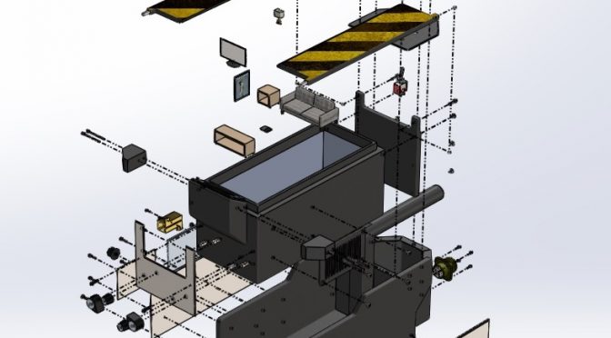
Printing Flexible Parts
SLS prints can be very flexible. The key is designing features that will allow the typical Nylon PA 12 material to flex where needed. 3D printing makes it very easy to pattern small intricate flexure features across a part. Each individual flexure only needs to bend a tiny amount to contribute to a larger overall bending across a part. The part is SLS printed in a static unflexed state and is immediately flexible when removed […]
Mechanical Design / Meta / Projects / Software
Posted on:
New Site for Mechanical Designs and Automation Ideas
I’m launching a new site to catalog mechanical designs and provide inspiration for automation equipment. automate.engineer I would call this a “design library” or “idea library” for mechanical equipment and automation. I’m a mechanical design engineer by trade and I haven’t found a good resource for collecting mechanical ideas or cataloging cool designs. My new site will try to fill that void. I’m building this for myself so I’m not sure what the utility or […]
3D Printing / Projects / Software / Solidworks
Posted on:
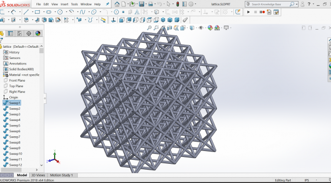
Importing Lattice Type Geometry into Solidworks
I’ve been daydreaming about some 3D printing projects again and have spent some time looking at the lattice style structures that are used as low density volume fillers in SLA or SLS prints. I think this is an underappreciated area of printing because these structures can only be created practically by printing and there is likely some interesting strength and stiffness optimizations you can do by tinkering with the lattice geometry. I think this will […]

Projects / Software
Posted on:
Satellite Weather Bot
8 hour loop – 03:54PM EDT – 07.10.2019 #wx #satellite #GOESEast #philly #nyc #dc #boston pic.twitter.com/GVuEUHVOIS — SatBot NorthEast (@Satellite_NE) July 10, 2019 ABOUT I’m a big fan of NOAA in general but I’ve fallen in love with the real time imagery available from their GOES-16 satellite. Weather nerds are all over this stuff but I don’t think the general public has any idea this space imagery exists. There are a few accessible points for […]
Machinery / Mechanical Design
Posted on:
Mechanical Design Idea Sources
Trying not to reinvent the wheel? Need a simple proven linkage, detent, clamp, or other mechanical widget? Here are my idea sources when trying to sketch out a mechanical design. Often the path of least resistance is reusing an existing design. Misumi Library – Downloadable designs for automation mechanisms, fixtures and small equipment. Everything is professionally designed. Some interesting and detailed content here. A hidden gem. 507 Mechanical Movements – A familiar resource for simple sketches of […]
3D Printing / Mechanical Design / Projects
Posted on:
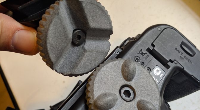
Magnetic Camera Mount
I’ve been looking to dip my toes into the 3D printing pool for a week or so now. I really needed a project that would be a good excuse to print some parts. I decided to start with the design of a magnetically fastened camera mount that would use a Maxwell kinematic coupling. I love kinematic couplings and used them in some cool automation applications in the past. They’re a great way to repeatably and […]
Machinery / Mechanical Design
Posted on:
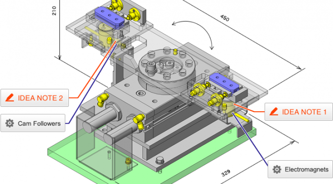
Mechanical Design is a Jigsaw Puzzle
I’ve been doing machine design for about 10 years and I often compare the mechanical design process to a creating a jigsaw puzzle. The most obvious parallel is that there are many pieces for both a machine and puzzle that must fit and work together. Even simple machines are broken down into multiple subassemblies that need to fit together like puzzle pieces. Each subassembly piece has to fit together in the process and in the context of […]

Petroleum
Posted on:
What is a Spoolbase?
A phenomenon adjacent to the Wikipedia rabbit hole may be Google Maps tourism. While reading the Wired article “The Inside Story of the Great Silicon Heist” by the excellent Brendan Koerner I was curious to look at the Mitsubishi polysilicon facility described in the article on Alabama’s Theodore Industrial Canal. While the facility wasn’t much to look at I did notice an interesting neighbor on the canal. A perfectly straight, mile-long piece of construction that butted up against […]