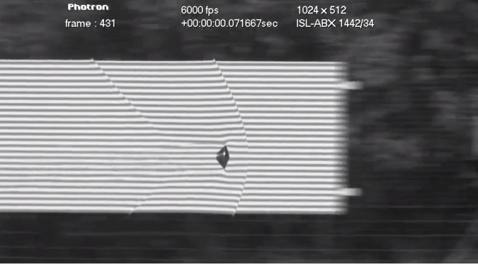
All posts by enginoor

Solidworks in 4K

I was recently awarded with a pair of 4K Acer B286HK monitors at work for my Solidworks workstation.  I was told there was an ordering mix up and they couldn’t be returned.  Not sure if that was the complete story but I was not going to complain.

Right off the bat, Solidworks looks great in 4K.  Assemblies look crisp and detailed, drawings appear sharp with annotations and dimensions crystal clear.  It took a few days to adjust to a higher DPI and I ended up making a few tweaks along the road to reduce eyestrain.  I wanted to share what I had learned to make things easier for other users going through the same transition.

First, adjust global scaling for Windows.  This seems like a necessity for all 4K monitors.  The actual text scale without increased scaling is a recipe for headaches and eye strain.  I settled on 175% after experimenting with a few different scale factors.  You can adjust this in Windows Display Settings – make sure you restart Windows afterwords.  This scaling adjusts text and program scaling globally but there are some strange scaling issues when programs don’t follow Window’s lead.

4K Display Scaling


Second, scale your Solidworks icons to make them usable.  I am a fan of the tiny icons without text but there’s a limit to how small I will go.  The adjustment for this is right at the top of the screen in Solidworks.

4K Solidworks Icon


Third, make sure both of your monitors are running at the same resolution.  The DisplayPort cables included with the new monitors were on the short side and one of the cables couldn’t reach from my desk to my tower on the floor.  For a week I was running the second monitor with a DVI cable and could only display a 1080p image through the cable.  The consequence was terrible graphics glitches in Solidworks due to the resolution mismatch.  My Solidworks viewport would flicker and have strange image buffer artifacts.

Lastly, buy longer DisplayPort cables ahead of time and avoid issue number three.


Building a Solidworks PC – 2016 Edition

Solidworks Icon

EDIT: This article has been updated in Building a Solidworks PC – 2017 Edition

Another year, another release of Solidworks.  2016 will bring a mix of incremental upgrades (an updated move triad!) and a few new features. This article is an update from my workstation build last year.  Not a whole lot has changed regarding a workstation build but it’s time to start considering Windows 10 and a beefier CAD GPU.  Overall there have been minimal performance relevant changes in 2016 and most of the hardware remains the same.

The core of a good Solidworks workstation is still a fast CPU, lots of RAM, and a Solidworks approved workstation graphics card.

Solidworks performance is limited by the CPU and unfortunately only runs single-core for everything except simulation and rendering.  An Intel i7-4770 processor will provide good performance for the price even if you’re using only a single core on the chip.

16GB of RAM is a minimum and important for dealing with large assemblies.  This stuff is cheap and can easily be expanded in the future.

A basic CAD workstation graphics card should be sufficient and won’t hinder performance.  They key here is stability and performance with Solidworks which is why you want something like the Quadro K4000.  Workstations graphics cards are essentially glorified gaming cards but they have extremely stable drivers.

Those are the important bits, the following list covers the complete build.  All components are from Amazon because they have fairly competitive prices and good customer service.  Shop around though, your experience may vary.

The system price at time of writing is is $1880.  Part prices are not listed here because they seem to change week to week.  Expect the system price to trend downward in the next few months.

Processor – Intel i7-4770 – good performance for the price

Motherboard – MSI Z97 PC Mate LGA – feature-rich motherboard to provide flexibility in the future, has a fancy BIOS and will support up to 32gb of RAM

Graphics CardQuadro K4000 – you’re paying for stability here

Memory – Kingston 16GB – fast and cost effective

Storage – Samsung SSD 840 EVO-Series 500GB – a nice solid state drive for speedy performance, I think it’s important to stick with a name brand here to ensure good performance over the life of the drive

DVD LG Electronics 24X – sigh, can’t quite escape physical discs yet.  With writing feature for all of your documentation purposes.

Case – Corsair Carbide Series 200R – a nice clean case that’s easy to work on

Power Supply – Rosewill 80 PLUS BRONZE 550W – Solid power supply with more than enough wattage, will support expansion in the future

OS Windows 10 Pro OEM – The new supported standard, if you don’t upgrade now you may be forced into it soon

That’s everything you need for a complete build!  The case comes with all necessary hardware and fans, the power supply has all the cables, and the CPU has it’s own cooler and heatsink.

Need monitors?  I’m a big fan of the 24-inch Dell Ultrasharp because of the positioning flexibility.  It’s easy to setup your dual monitor view in any configuration.  Ergonomics are a big deal if you’re sitting in front of monitors for 8+ hours a day.

Viewing CAD files in VR

vr

Virtual reality has suddenly arrived. Headsets such as the Oculus Rift and Valve Vive are near a consumer release and offer immersive VR experiences. While most of the hype has been surrounding VR video games there is a huge market for VR visualization of 3D CAD files. Conceptual factory layouts, machine assemblies, and architectural plans can all be visualized in VR prior to release.

Engineers and designers can use VR to evaluate the human interaction and ergonomics of conceptual designs. VR will be an excellent sales tool by allowing potential customers to visualize the scale and impact of a final design, something especially important in architecture.

Currently there is no native VR support for any of the major CAD packages but there is a simple workaround for viewing any CAD data in VR. While most native solid CAD files are almost impossible to interchange, generic 3D files like STEP can be opened by almost any 3D modeling program.

Video game engine packages such as Unity and Unreal are free to download and use and offer direct Rift and Vive support. You can use these packages as glorified model viewers by importing generic 3D files and using their direct VR viewing mode.

Here’s what the workflow looks like:

Native: Solidworks, CATIA, Inventor, Sketchup

Save as intermediate: .STP, .3DS, .STL, 3D .DXF

Import into VR Environment: Unity, Unreal

This workflow can export Solidworks, Inventor, CATIA, and SketchUp files to the Oculus or Vive. There are multiple intermediate formats to exchange the data, some experimentation may be necessary to find the best one for your CAD package. If you can’t find a direct exchange format you may have to use another 3D modeling package, such as Blender, as an intermediate. Blender has a ton of export formats including .obj and .fbx

Acoustic Camera

This is a neat gadget that’s like an acoustic version of FLIR.  Technology like this is becoming more important as consumer products and stringent safety regulations are requiring more acoustic analysis.  This could be very useful to quickly locate and troubleshoot annoying rattles in an industrial plant.

Manufacturer page here

acam

High Speed Chip Placement

This is the Samsung SM421 surface mount chip placement platform (not to be confused with the SM421 showerhead).

The machine vacuum picks 6 tiny SMD components from cassettes in the front of the machine and moves to place them on a fixtured PCB.  The high speed precision and motion is amazing.

This video may not have the best clarity but the camera angles show a lot of the machine mechanics.

The individual axes are ballscrew driven and the flashes of red light are from a vision inspection process to check if each component has been picked correctly.  There’s a vision camera on the front of the placement head that appears to be used for PCB fiducial recognition or part inspection.

I’d like to learn more about the placement head because it’s not immediately apparent how the individual chip feeders are vertically actuated.  There are some clues that they’re belt driven but it’s still somewhat of a mystery.

Samsung SM421 Samsung SM421 Fixturing

Samsung SM421 data sheet

Assembling a Very Large Machine

How do you assemble a giant machine tool?  Very carefully.  A lot of thought needs to be put into the machine design early on to accommodate assembly, alignment, shipping, and installation.  Simple things like providing lifting points and making sure fasteners are easily accessible can help things go smoothly in the field.

The above video shows a time lapse of the installation of a Waldrich Coburg Powertec gantry style machining center for customer MAN Diesel.  There’s a lot going on so I’d like to break down the individual installation steps.


Pouring the Machine Foundation

PowerTec Bed Foundation

The installation starts with the machine bed foundation.  This is the foundation that will support the X-axis beds and ultimately the entire machine weight.  A thick foundation with a lot of reinforcing bar is important to minimize deflection in concrete due to the machine movement and operation.  Any deflection or settling in the foundation will ruin the machine precision relative to the workpiece.


Pouring the Workpiece Foundation

PowerTec Work Piece Foundation

The workpiece requires an isolated bed foundation.  Similar to the machine bed foundation, stiffness is the key.  Any deflection in either of these foundations relative to one another will ruin the machine precision.


X Beds

PowerTec X Beds

Installation of the X beds is an important step and one they appear to skip over in the video.  The X beds are anchored to the bed foundation and will ultimately form the X-axis of the machine.  The beds support and guide the machine with linear rail.  Straightness of this rail is critical to the machine precision and must be adjusted during installation using jacking screws built into the beds.  Some of this process is shown in the video. Gear rack for driving the machine must also be adjusted and spaced correctly during this process.

Installation of the workpiece fixturing plates is also shown during this stage.


Waycovers

PowerTec Way Covers

The X axis way covers are installed to keep chips and debris away from the X rails.  Interesting they’re installed this early, they can dent easily.


X Axis Carriages

PowerTec X Carriages

The X axis carriages are lifted and mounted to the X rail.  It depends on the style of rail but the bearing cars are likely already installed onto the rail and carriages are bolted down to the cars.


Z Towers

PowerTec Z Tower

The gantry legs with integrated Z axis are installed next.   They’re flown in via the overhead crane, stood up, positioned and installed onto the X carriages.  It appears that all of the necessary fasteners are installed prior to the legs being set into place.


Y Bridge

PowerTec Y Bridge

The Y bridge is flown into place and ties the two gantry legs together.  This takes some coordination with the crane operator and some time spent in the man-lift. The maintenance platforms and electrical cabinets also appear to be installed behind the gantry during this process.


Y Axis

PowerTec Y Axis

A tricky part of the installation.  It looks like they place the Y-axis on blocks during the installation process.  Careful positioning is required to attach the Y-axis to the bearing cars and ball nuts on the tower legs.  It’s important to make sure these fasteners are easy to access during the design phase.


Z Ram

PowerTec Z Axis

The Z-ram is bolted onto the Y-axis without a lot of hassle.  The assembly is lifting by red painted installation tooling bolted to the sides of the lower assembly.   Note the whole Y axis assembly is still resting on blocks.


Operator Platform

PowerTec Operator Platform

A movable operator platform is installed and bolted onto the front of the machine.  This makes getting right up to the tool point easy for the operator.  I’m speculating that this is for automated tool changing as well.


Alignment

PowerTec Alignment

Axis alignment occurs before all the final way covers and bellows are installed.  Important to make sure everything has been installed correctly and running smoothly.  Most of the axes are modular but there can be some tricky alignment in the Z-axis due to the tandem configuration.


Assembly Complete

PowerTec Complete

Minor details such as decking and cell guarding are installed, the machine is bought off in a factory acceptance test, and everyone gets to go home!


Large Envelope Mill for Wind Turbine Blades

This has an impressive envelope for a mill and is used in the manufacturing process of wind turbine blades.  I initially guessed this was for composite trimming operations but the manufacturer lists the machine for work with “polystyrene, resins and fibres.”   This is possibly used for form or blade core manufacture?

This is a high-rail gantry style mill which can make part loading more difficult due to the mill legs but ultimately decreases the moving mass of the machine.  The numbered assembly hanging off the gantry appears to be a tool changer.

Manufacturer link here.  No information on tolerances.

Wind Turbine Blade Mill Tool Changer

Building a Solidworks PC – 2015 Edition

EDIT: This article has been updated in Building a Solidworks PC – 2017 Edition

The core of a good Solidworks workstation should be a fast CPU, lots of RAM, and a Solidworks approved workstation graphics card.

Solidworks performance is limited by the CPU and unfortunately only runs single-core for everything except simulation and rendering.  An Intel i7-4770 processor will provide good performance for the price even if you’re using only a single core on the chip.

16GB of RAM is a minimum and important for dealing with large assemblies.  This stuff is cheap and can easily be expanded in the future.

A basic CAD workstation graphics card should be sufficient and won’t hinder performance.  They key here is stability and performance with Solidworks which is why you want something like the Quadro K2000.  Workstations graphics cards are essentially glorified gaming cards but they have extremely stable drivers.

Those are the important bits, the following list covers the complete build.  All components are from Amazon because they have fairly competitive prices and good customer service.  Shop around though, your experience may vary.

The system price at time of writing is is $1495.  Part prices are not listed here because they seem to change week to week.  Expect the system price to trend downward in the next few months.

Processor – Intel i7-4770 – good performance for the price

Motherboard – MSI Z97 PC Mate LGA – feature-rich motherboard to provide flexibility in the future, has a fancy BIOS and will support up to 32gb of RAM

Graphics CardQuadro K2000 – you’re paying for stability here

Memory – Kingston 16GB – fast and cost effective

Storage – Samsung SSD 840 EVO-Series 500GB – a nice solid state drive for speedy performance, I think it’s important to stick with a name brand here to ensure good performance over the life of the drive

DVD LG Electronics 24X – sigh, can’t quite escape physical discs yet.  With writing feature for all of your documentation purposes.

Case – Corsair Carbide Series 200R – a nice clean case that’s easy to work on

Power Supply – Rosewill 80 PLUS BRONZE 550W – Solid power supply with more than enough wattage, will support expansion in the future

OS Windows 7 64-bit OEM – The old standard here, I prefer it over Windows 8

That’s everything you need for a complete build!  The case comes with all necessary hardware and fans, the power supply has all the cables, and the CPU has it’s own cooler and heatsink.

Need monitors?  I’m a big fan of the 24-inch Dell Ultrasharp because of the positioning flexibility.  It’s easy to setup your dual monitor view in any configuration.  Ergonomics are a big deal if you’re sitting in front of monitors for 8+ hours a day.


Move with Triad

Solidworks Triad

This is by far my favorite Solidworks feature that no one seems to use or even know about.  It’s called “move with triad” and it makes working with assemblies much easier.  Right click on any part in an assembly and it should be an available option.

Triad Menu Option

The triad tool allows you to constrain part translation or rotation to a single axis.  This removes a lot of frustration when positioning parts in an assembly prior to mating them.  The flexibility to position things easily can really speed up machine layout and concepting when things are loosely defined.

The triad can also help you locate parts lost in larger assemblies or move parts that have gotten lost inside other solids.

Bind it to your “T” key now!